|
|
|
Panagiotis Chaviaropoulos (a), Andreas Vossinis (b), Spyros Voutsinas (b)
(a) C.R.E.S., 19km Marathonos Ave., 19009 Pikermi Attiki, Greece
Tel: (+)301-6039900, Fax: (+)301-6039905
(b) N.T.U.A., Dept of Mechanical Engineering, Fluids Section,
P.O. Box 64070, 15710 Zografou, Athens, Greece
Tel: (+)301-7721096, Fax: (+)301-7721057, email: aiolos@fluid.mech.ntua.gr
In view of exploiting wind energy with higher efficiency, the design of wind turbine rotors must be revised in all aspects. Of course, the aerodynamic part is quite important since it defines the component that captures energy from the wind. Given the blade, other parameters come into play, such as the control, the compatibility with the grid, the structural characteristics etc. So although a global optimisation problem could be formulated, it is advisable at a first level to consider the aerodynamic optimisation of a blade.
The physical process that underlies the energy capturing is driven by the overall geometric characteristics of the blade (e.g. the chord and twist distributions) and the aerodynamic performance of the airfoil sections that form the blade. At small or moderate angles of attack, where the behaviour of the airfoil is linear, the value of minimum drag dominates quantitatively the energy capture. The range of this part is extensive enough so as to justify a design aiming at low drag airfoils. Of course the lift is also important, but its variation up to maximum lift coefficient can be controlled by the thickness and camber.
Another parameter which has been discussed several times is the sensitivity of the airfoil performance to roughness [5]. From the airfoils in wide use, the NACA 63xxx have more or less this property at least at moderate thicknesses. However, their behaviour near and after stall is not as smooth as required. On the other hand, the overall performance is not the best possible.
2. OVERVIEW OF THE DESIGN PROCEDURE
The design of a rotor is formulated as a maximisation problem
with cost function the annual energy production for given wind
distribution. In the cases considered so far the turbine is considered
to be stall regulated which is the worst in terms of loading and
of dependence on the blade sectional characteristics. Other types
of control will be examined in future.
The design strategy for the blade can be defined as a three step process:
Step 1: DEFINITION OF THE BLADE GEOMETRY
The optimisation problem is defined using as design variables the chord distribution, the sectional lift and drag behaviour, the radius and the rotational speed.
Step 2: DESIGN/SELECTION OF AIRFOILS
The target lift and drag curves obtained from Step 1, are input to the airfoil design module which provides the curves corresponding to feasible airfoils.
Step 3: ASSESSMENT OF THE DESIGN
The performance of the rotor with the "real" curves is calculated and final results are obtained.
Step 2 can be tricky. Following traditional optimisation procedures according to which the lift and drag curves are appropriately parametrised, it might come out that the target aerodynamic behaviour cannot be accomplished. To avoid such difficulties, instead of specifically designing airfoils, profiles from a data base were selected. Now, Steps 1 and 2 will be looped until convergence. A Genetic Algorithm was developed to carry out this process (See [1] for more details).
The data base from which the blade design module selects its items, was filled with specifically designed low drag airfoils. The design of such airfoil shapes is performed for given Reynolds number according to the following procedure:
Step 1: SELECTION OF THE DESIGN POINT
Based on previous experience, for each airfoil, a desired target lift coefficient is selected. It is chosen to fall near the middle of the laminar pocket where lift is linearly increasing and drag assumes its minimum.
Step 2: DETERMINATION OF THE PRESSURE DISTRIBUTION
The pressure or equivalently the inviscid velocity distribution over the airfoil is determined simultaneously for both sides by solving a minimisation problem for the drag (as expressed by the Squire-Young formula) in order to:
(a) Attain the target lift and
(b) Satisfy the boundary layer equations using the Cebeci-Smith model.
It is assumed that the lengths of the two sides are approximately equal which is the case since the design point corresponds to a low incidence. Suitable velocity parametrisations are defined using splines. On each side end conditions are imposed (Fig.1). At the trailing edge the common velocity VTE ( almost equal 0.85 U ( where U is the velocity at infinite)) as well as the slopes B1 and B2 were given whereas at the leading edge linear variation for both sides was set with given slopes A1, A2 over prescribed lengths S1 and S2 respectively.
Step 3: SHAPE DETERMINATION
By means of an inverse potential solver a first form of the airfoil as well as incidence at which the target lift is attained, are obtained. Within this step, the closing of the airfoil shape is performed automatically, as described in [3]. Finally a polynomial interpolation at the leading edge is used in order to get a smooth and rounded nose.
Different airfoils can be constructed, for the same design CL, by adjusting the end conditions of the velocity parametrisations. To increase the thickness, the angles A1 and A2 must be increased. The same trend was obtained by increasing the lengths S1 and S2. To adjust the camber, the slopes at the trailing edge must be changed. Thus a family of airfoils was constructed. The entries of the data base were classified according to their relative thickness and thus grouped as hub, mid-span and tip blade sections. For each airfoil, XFOIL [4] was run to provide the lift and drag curves. The runs were performed for Re = 2*106 with tripped boundary layer transition on the upper surface and free transition on the lower surface of the airfoil. The data base has now about 100 records. It is expected to double the number of airfoils in the near future with high lift airfoils as well.
Typical results are shown for 14% and 18% thick airfoils. In both cases two examples are included with different camber which are compared with the corresponding NACA 63xxx airfoils. In Fig.3,4,8 and 9 all curves correspond to untripped XFOIL calculations. In Fig.5,6,10 and 11 the untripped calculations (UT) are compared with tripped (T). In Fig.5,6 data provided by RISOE are also shown. It can be noted that the type A airfoils which are close to the NACA behaviour in the linear part have lower drag. On the other hand type B exhibit higher drag values but at much higher lift. When roughness is added, significant loss of energy may occur. However even in this case the new type B airfoil still behaves better than the corresponding NACA especially at high incidences. This means that instead of trying to make roughness independent airfoils, the designer can select airfoils that work well as tripped.
Finally an example for a 30% thick section is presented in Fig.12,13,14. In this case it was not possible to attain the design CL. The method assumes that the two sides of the airfoil have approximately the same length which is equal to the chord. This is evidently not valid when the thickness reaches high values. Experience showed that the method works well approximately up to 25-26%. Anyhow beyond this thickness airfoils are used to smoothen the passage from the cylindrical to the aerodynamic part of the blade.
The work has been partially financed by the Greek General Secretariat of Research and Technology, under the EPET-II #573 project.
[1] M. A. Belessis, D. G. Stamos, S. G. Voutsinas, Proceedings EUWEC (1996).
[2] P. Chaviaropoulos, Inverse Problems in Engineering (1996), to appear.
[3] P. Chaviaropoulos, V. Dedoussis, K. D. Papailiou, Computer Methods in Applied Mechanics and Engineering 110 (1993) 131.
[4] M. Drela, Proceedings Low Reynolds Number Aerodynamics Conf., Ed T. J. Mueller (1989) 1.
[5] D. C. Hill, A. D. Garrad, Proceedings EWEC (1989).
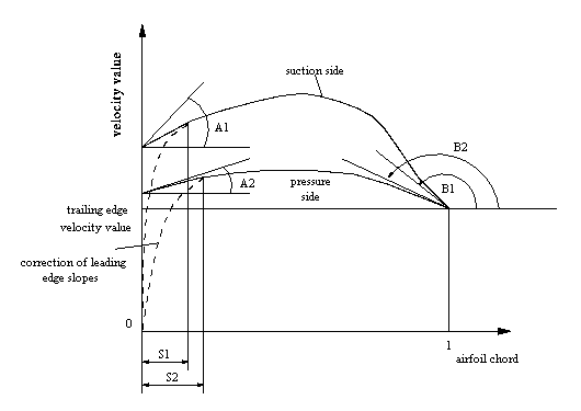
Figure 1: The parametrisation of the velocity distribution.
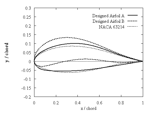
Figure 2: Tip airfoils.
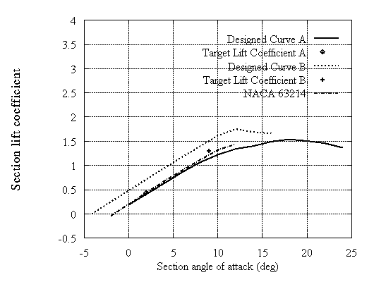
Figure 3: Calculated lift coefficient curves for tip airfoils
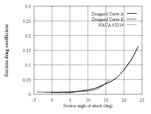
Figure 4:Calculated drag coefficient curves for tip airfoils
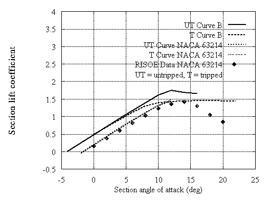
Figure 5: Lift coefficient curves for tip airfoils
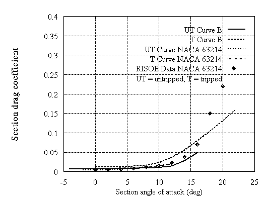
Figure 6:Drag coefficient curves for tip airfoils
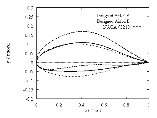
Figure 7:Mid-span airfoils
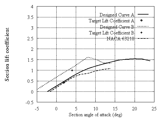
Figure 8:Calculated lift coefficient for mid-span airfoils
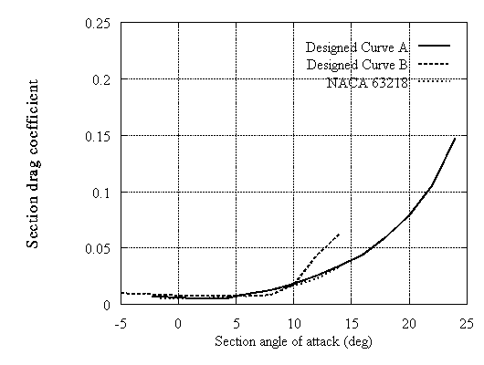
Figure 9: Calculated coefficient for mid-span airfoils
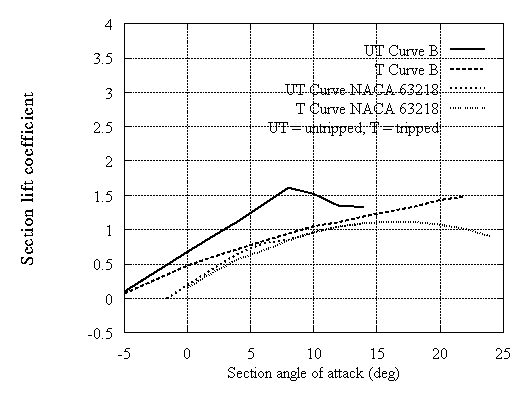
Figure 10:Lift coefficient curves for mid-span airfoils
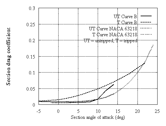
Figure 11:Drag coefficient curves for mid-span airfoils
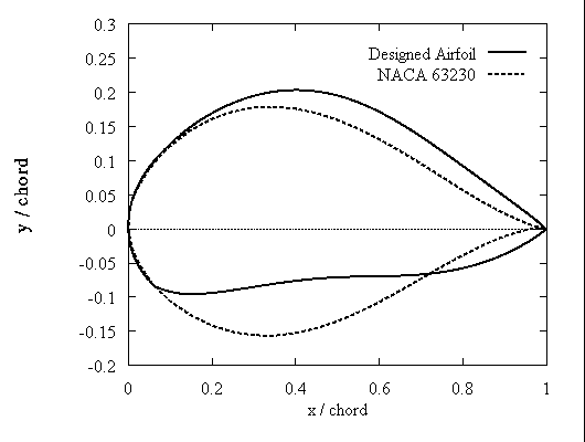
Figure 12:Hub airfoils
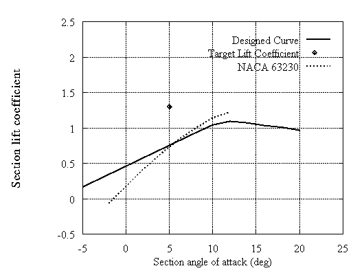
Figure 13:Calculated lift coefficient curves for hub airfoils
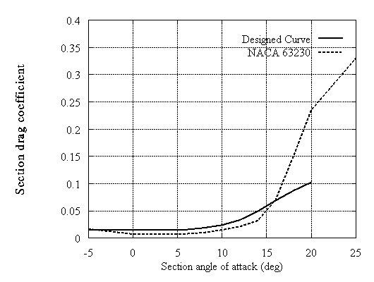
Figure 14:Calculated drag coefficient curves for tip airfoils
|
|
|
|
|
|